
So you've bought a NyquistNightmare!? Why?? Hopefully you can answer that, but if not, here's what this weird module is, and can do:
There's two VCOs in here in series with each other -- the input signal controls the frequency of the first one, and the output of the first one controls the frequency of the second one. The result gets passed to a high-pass filter, then a low-pass (resonant) filter. The result of that is wet/dry faded with the original signal, and the "effect volume" knob will attenuate the "wet" signal.
How does it sound??? It destroys signals. My original goal was to literally transmit audio over AM radio frequency in a Eurorack module. That's a dubious goal, and for several reasons never happened. Instead, this uses frequency modulation to encode a signal into a high-frequency (not radio frequency, but the VCOs can go ultrasonic) wave, and the 2nd VCO demodulates the signal. This is all depending on the top four knobs, the left two attenuate the CVs going through, and the right two control the frequencies of the "carrier" wave.
If the carrier waves are set to the same frequency, and the attenuation is set correctly not to distort the signal, you can achieve an output signal that quite resembles the input signal.
My favorite way to use this module is to process movie dialogue. It can create squeals and bleeps by itself, and sending LFO or audio-rate signals into the CV inputs can get modem-sounds out of it.
WHAT YOU WILL NEED:
- The PCB set
- 2 1M green sealed linear potentiometers
- 5 100K green sealed linear potentiometers
- 2 10K green sealed linear potentiometers
- 4 Thonkiconn 3mm mono jacks
- 1 10-pin IDC header (I prefer boxed to reduce frustration)
- 4 3mm LEDs, any color
- All the assorted tools you need for all electronics projects

First, break the PCBs apart.


First, install the power header. Be mindful of the orientation of the plastic box-shroud.

There's the solder-side for the power header.

Make sure the potentiometer legs are straight so they'll fit properly into the PCB
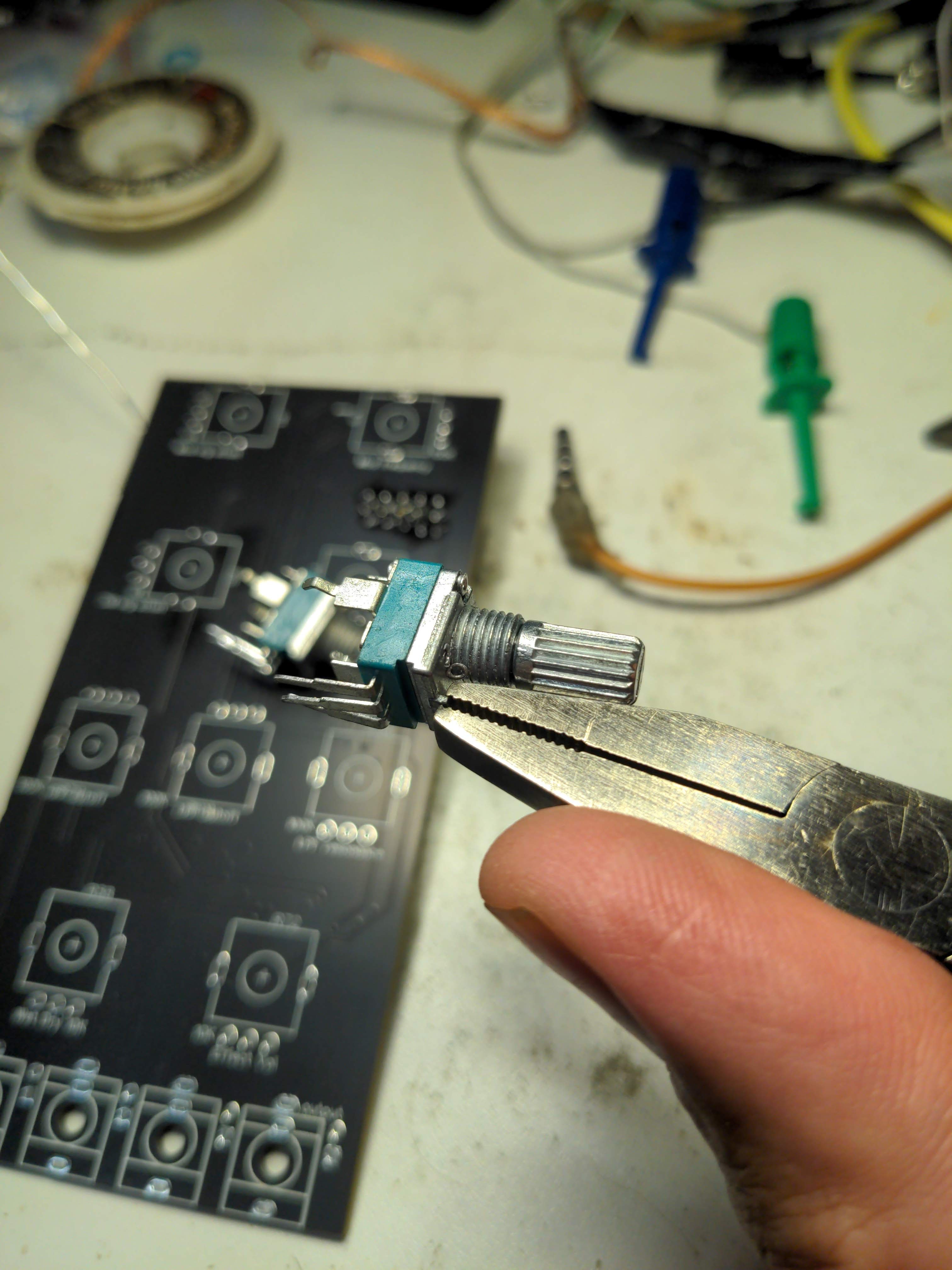
Also, the pots probably have a locator lug thing you'll want to break off

Place the nine potentiometers in the PCB where they're supposed to go -- follow the PCB markings

Put the Thonkiconn jacks in place too!

In order to make sure the faceplate fits correctly, you'll want to place it before soldering all the potentiometer and jack legs

There's the faceplate all snug in place where it's supposed to go

Put the washers and nuts on. If you're using smaller potentiometer knobs for the pots with smaller graphics around them, don't install washers and nuts on those.

Solder all those bad boys down!

Here it is, all soldered up

Putting LEDs in the jack holes is entirely optional, but it allows cool light to shine through the jacks, which can help guide your hand when panic-patching in dark places. Any color will do, and you can choose different colors for different holes, that'll all work fine. Make sure the longer leg of the LEDs are closer to the bottom edge of the PCB

Snip the legs of the LEDs, bend them over about 90 degrees, then bend them more to go into the PCB. If you mess up and put one of the LEDs in backwards, none of them will light up (they're all in series with each other). You can figure it out though.

That's how it should look. You may want to clean the flux from the PCB, depending on your aesthetic sensibilities and if you use "no-clean" solder, which is what I do but it looks messy uncleaned. You can use whatever knobs you like as long as they fit. The four potentiometers with smaller graphics around them (which you may not have put nuts on?) can use smaller knobs if you have them. Large guitar-style or chicken head knobs won't fit, probably, but all typical medium-sized knobs will be okay.
With that, you're finished! Plug the module in (polarity protected, so don't worry anything's going to explode) and see what sounds you can get! Please enjoy!!!


No comments:
Post a Comment