Sunday, August 20, 2023

ZVHP high-pass VCF build guide!

Edit: I just realized that I've already told most of this story in my July 4, 2023 post. uh..... sorry? I finished that post up by saying "golly I hope the 2HP filter works" and it does, so here's this post:


It's the ZVHP high-pass filter! In PCB form!!!

I met Konstantin (Constantine??) at Knobcon 2017, and one of the pieces of advice he told me was "put your kick drums through a high-pass filter then a low-pass filter." I was like what are you talking about but I took his advice, first scouring the Internet for good high-pass filter designs, rejecting most of them as too harsh.

Sorry..... digression...... the most common variable-state VCFs have insane uncontrollable resonance. Thomas Henry fixed that with his excellent VCF-1 design, but I didn't find that one until later. Notice the 10pF capacitors C1 and C2 -- those are the magic capacitors that stop the filter from becoming uncontrollable. Digression done.


The other design I rejected was the VERY VERY GOOD Polyfusion high-pass filter. Ron Folkman (whom I met at Knobcon 2018)

Mr. Folkman's high-pass filter was very controllable, wonderfully designed, and his hand-drawn schematic... my stars, they are artistically gorgeous. Maybe you can tell I'm sorta crushing on him in that picture. 

Anyway, I rejected Ron's filter for kick drum filtering because it is a four-pole filter, making the cutoff too steep for my ear for that specific purpose. I took the design, cut it in half, struggled mightily with the resonance part of the circuit, and when I finally came got something that worked, I found that it worked very well indeed!

So anyway, here it is. I'm really proud of this design. It's one of the first times I felt like I really understood the functioning of each part of the circuit, and could take ownership of the design as uniquely mine.

Okay, build guide time.
First, break the PCB into pieces.

 Smooth the edges of the PCB where the breakoff bits are, especially on the panel.


Then, install the pins that the perpendicular PCB will slot into.


Jacks. Put the Thonkiconn jacks where they go. Solder them in.


Potentiometers. These are 100K linear Song Huei tall trimmers. I usually buy these from Synthcube. Don't solder these in, just place them on the PCB, and then put the faceplate on, installing the nuts on the jacks to hold the front panel where it needs to be. 


Wiggle the potentiometers around on the PCB until you're happy with how smooth and straight they are. Use some pliers to slightly squeeze the mechanical legs of the potentiometers. This way that metal part should let the module fit in your modular. Finally, solder the electrical and mechanical connections to make stuff all sturdy and tight.


Now it's time to mess with the electronics! 


You'll need three 100K box trimmers and one 10-pin shrouded header for the Eurorack power.

The notch in the power shroud goes away from the electronics side of the PCB. Pin 1 of the cable (the red wire) goes where the PCB says "RED STRIPE" anyway, be careful to get that part right.


The trimmers can lay over so they're in the same plane as the PCB.


Now you get to connect the PCB to the rest of the module!!! Never more to be parted. Forever and ever. Amen.


Now it's time for LEDs. This is optional, but who doesn't want light to shine out of their jack holes! I am not a person who doesn't want that, that's for sure! The long leg goes in the square pad. 


Be careful with the legs of the top LED so they're not touching each other or the resistor that's right under them. 


Okay, calibration time. Your trimmers are probably 25-turn pots, and they're probably from the factory set right in the middle at 12.5 turns. Assuming that's the case, start the calibration process this way:

Range trimmer: counterclockwise 8 turns
Scale trimmer: clockwise 4 turns
Resonance limit trimmer: counterclockwise 8 turns


These trimmer settings are a good starting point. Plug a signal into the In jack (something with rich harmonics, a saw, perhaps), listen to the Out jack, and adjust the trimmers more to get the filter dialed in just right.

The range trimmer sets the center frequency of the cutoff knob on the front of the module. Turn it counterclockwise to get the filter higher pitched, clockwise to get it lower pitched (in Rev. 2 this will be swapped).

The scale trimmer adjusts the exponential response of the frequency. If you're careful with this trimmer, and you've set the resonance to self-oscillate, you can use this filter as a 1V/Octave oscillator. It won't be temperature stable, and the response will change with the resonance knob, but it will probably be within a few percent over a couple octaves at least. I've never tried it myself...


The resonance trimmer sets the gain of the feedback signal -- higher gain, more oscillation. This is easy to dial in -- leave the In jack without anything in it, turn the cutoff knob to maybe 9 o'clock, turn the resonance knob all the way up, and adjust the resonance limit trimmer until you're happy with the sound of the resonance. 

You should have your ZVHP all dialed in, ready to go! I love what this filter can do to kick drums, turning them into monster low boom sounds, muting them up to little clicks, or turning them into a little bongo sound, depending on the resonance and cutoff. I hope you find yours as enjoyable.

Saturday, August 19, 2023

DumpsterDelay

So you want a delay module, but want to put a dumpster filled with stuff in the feedback path? Great!

This is a fairly simple PT2399 delay module with voltage-controlled delay time. But here's the trick, there's lots of stuff to do with the audio while it's looping back to the delay chip. Of course, you can omit the dumpster filled with stuff and just have a solid delay. But the extra stuff makes it more interesting!

First, there's the two Piezo discs that you'll have to stick together back-to-back. They become an electromechanical way to pass the signal. There is resonance to this system, though, so there will be unpleasant shrieking as the resonance reinforces itself on each pass through the delay. There's many ways to deal with this, most of them mechanical, by damping the Piezo discs with electrical tape (my favorite), glue, foam, poster putty... and also there's two multiple-feedback notch filters on the PCB that will let you squelch any particular frequency with calculated resistor values. We'll cover that later, and don't worry, if you don't want to use the filters, just leave the resistors out.

First, break the PCB faceplate from the electronic part. You'll want to file or sand the bumpy edge of the faceplate for sure, and the bumpy edge of the PCB as well if you care about that kind of stuff.

There's the PT2399 chip installed on the PCB. I may have already installed the chip myself, but perhaps you've got a PCB without it. I will leave it up to you to figure out how to do this.

Let's install the trimmer, pin headers, and power header. Make sure you install the 10-pin shrouded power header correctly.

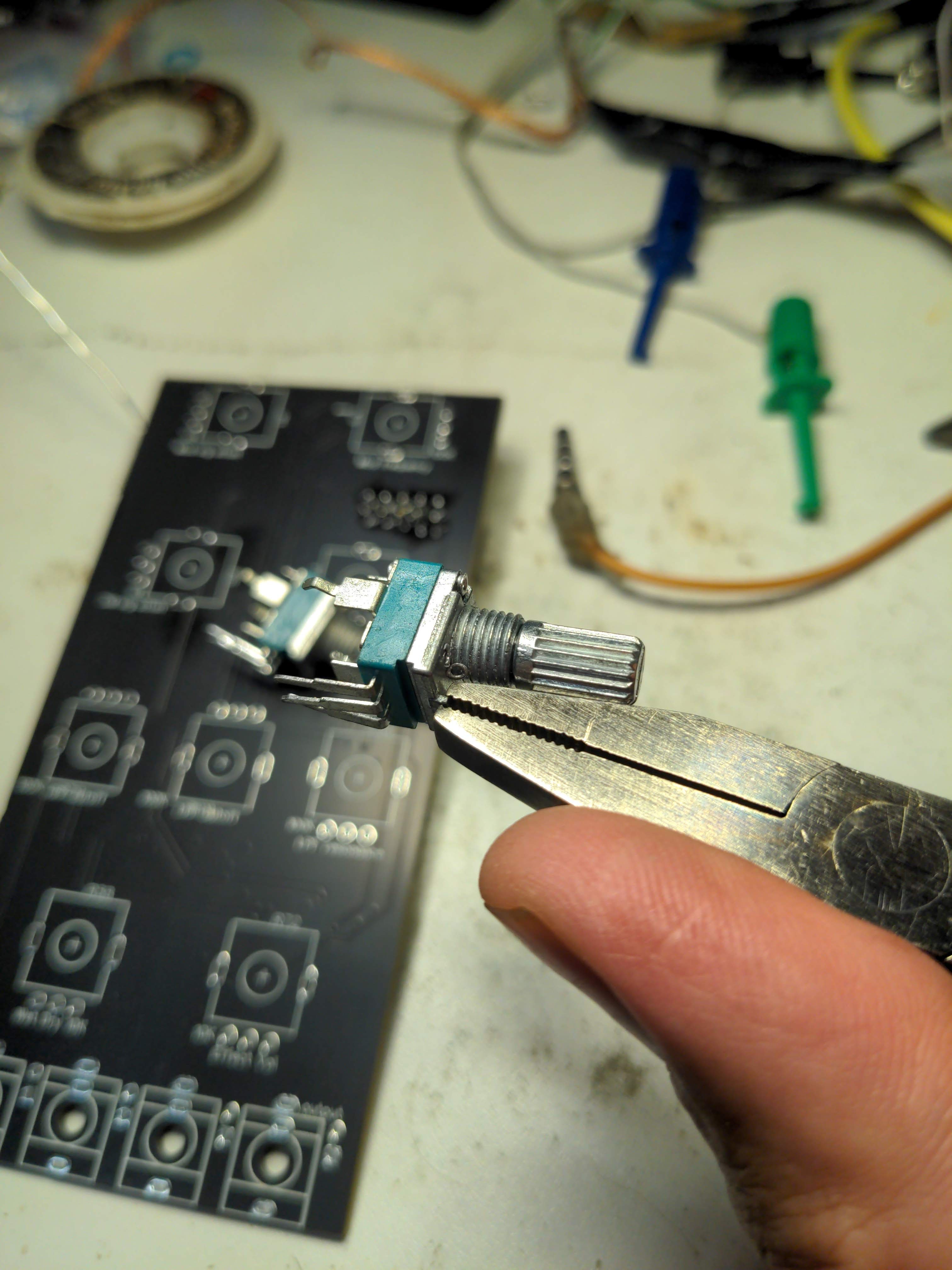
On the other side of the PCB you'll find spots for the 5 100K potentiometers, the 10K potentiometer, and the audio jacks. Snap the parts where they go but don't solder them quite yet. Also, break off the locator tab on each potentiometer if you've got pots that have them.

There they are snapped in place.

Before soldering these parts, put the faceplate on. Wiggle the parts as needed to get them all properly in the holes where they go. Probably you'll be able to turn the project over and solder everything in place now without installing any of the nuts, but if you do want to install nuts, that'll make things more secure.

Now it's time to mess with the Piezos. You might have to solder leads on to the Piezo discs, which may be a hassle. The middle part of the Piezo can be tricky.

The best way to do this is to get the wire leads tinned with plenty of solder. The outer ring is fairly easy to solder to. To get the wire to stick to the middle section, use a tool to hold the tinned wire securely to the whitish part of the Piezo, and use your iron to just get the solder on the wire melted, and take the iron away while keeping the wire held in place. This should work just fine -- the solder joint may look "cold" but if you wait for the solder to flow onto the Piezo, you can melt off whatever that coating is.

There's a picture a few down from here that shows what that looks like.

There's my Piezos with leads attached. It will be obvious by looking which wires are connected to the outer ring of the Piezos, and this will be important in a minute or two.

There's some superglue. You may choose double-sided tape, foam tape, another kind of glue, anything you want, but this is what I chose for this build. You will need to stick the flat side to the flat side. It's okay that the metal will be in contact with each other, but not necessary.

There's the Peizos 

Okay, notice that the wires going to the metal outside ring part of each Peizo are soldered to the "lower" pad of where the device attaches to the PCB. On each part, the outside ring gets connected to the pad nearest to the component label, U5 and U6.

Oh, I forgot to mention earlier, if you want to skip the Piezo devices, you may totally just jump the top two Piezo pads together -- the two pads opposite the component labels. That will pass the signal straight from the Piezo driver amp to the Piezo pickup amp.

Also, here's an opportunity to show that in order to pass the audio signal through the feedback path, you'll need to put a jumper across the "top" pair of pins. The jumper in this picture is yellow.

ALSO, there's a little resistor installed there in the middle of the picture. In this build, it's a 68K part, which works well. You may need a larger value (will be louder) or a smaller value (will be quieter). The trimmer adjusts the amplitude of the signal getting sent to the driven Piezo element, which will let you adjust the volume of the feedback signal.

Okay, it's LED time. These are entirely optional, don't install them if your power supply is close to the edge, but install them if you want cool light to pass through your audio jack holes.

On the first revision of this module (pictured here) the silkscreen for the LEDs is on the wrong side of the PCB. Just remember that in this project, square hole = pin 1 = longer leg of the LED.

Put the LEDs into the holes opposite each jack. Install the LONG leg of each LED into the square pad on the PCB. Kinda bend the legs over so they go into the pads and solder them in place.

You can see the LED legs sticking up through the PCB.

After snipping off the LED legs (and the resistor legs too, I guess) it's time to put the faceplate on. Don't put a nut on the CVAtten potentiometer since you may want to use a narrower knob on that one.

Okay go ahead and put all the knobs on, I guess (not pictured)

Here's the chunk of protoboard and where it goes. NOTICE: the +12V and -12V labels go toward the "top" of the module. If you put the perfboard the other way, you'll be shorting both power rails to ground, which is a bad idea don't do that.

If you have to build this module in a hurry, you can use a jumper wire between the "Audio in" and "Audio out" pads as I have done in this picture.

There's another picture of the jumper wire and the orientation of the perfboard.


"BUT JUANITO" I hear you say, "WHAT ABOUT ALL THOSE RESISTORS FOR THE MFB NOTCH FILTER???"

  So glad you asked. If you choose to dampen the resonant frequencies of the Piezo element electronically (which is a great idea -- mechanical dampening may change properties over time, but it's unlikely the Piezo resonances will change, and the notch filters will be stable over time as well), here's what you'll need to do.

Power the module up, turn the DelayTime knob to about 12 o'clock. Turn the Repeats knob to maybe 1 o'clock. Turn the wet/dry knob all the way wet. Listen to the output (with an amplifier, this output can't drive headphones), turn the Repeats knob up or down and listen to the frequency that's most obnoxious. 

Use a tone generator website like this one to determine what frequency you'd like to reduce. Or use a guitar tuner? Once you've decided which frequency to squelch, use this small Windows app (sorry it's Windows only BOOO) and convince your computer to let it run. Use a virtual machine to sandbox it if you're nervous... or figure out the math and do the calculations without a tool. 

Make your app look like that, with the Cap(nF) reading 10, the Gain reading 1, and the Q reading 7. Choose which frequency you want to attenuate (I've chosen 2000 here) and click the "Calculate R" button. It'll then look like this:

Look at that! The values you'll be able to get from your resistor bundle won't be this precise but we can try our best. If this were my build, I would choose 47K for R1, 680R for R2, and maybe measure a batch of 5% 100K resistors to find one near 96K for R3. You'll have to install the resistors on the "front" side of the PCB.

Of course, the two notch filters resistors correspond like this: R1 is R101 for the first filter, and R201 for the second. R2 is R102 and R202, likewise for R3.


Once you're happy with how the feedback path sounds, as resonant or non-resonant as you want, you will be able to adjust the trimmer and change the resistor in the middle of the PCB if you want.

First, the trimmer. Power up the module. Plug a signal into the in jack, with the Input Atten all the way up. Turn the DelayTime knob to 12 o'clock. Turn the Repeats knob all the way up. Turn the wet/dry knob all the way wet. Listen to the output and adjust the trimmer until you're happy with how runaway the feedback gets. Turning the InputAtten knob up and down can give you an idea of how the delays will run without additional signal being added. I prefer to be able to get the feedback running away when the Repeats is turned all the way up, because you can always turn it down.

Next, let's make sure the wet output is about as loud as the dry output. Plug some audio into the IN jack -- a song or drum loop is good, this isn't really possible with a solid tone. Turn the InputAtten knob all the way up. Turn the Repeats knob all the way down so it's just repeating once, slapback style. Turn the wet/dry knob to 12 o'clock. Are you happy with how loud the slapback delay is? Too quiet and it won't be satisfying, but if the slapback is louder than the original signal it sounds weird.

If you're not happy with the wet/dry amplitude, you can choose to tweak it with the trimmer, but remember that the trimmer also adjusts how loud the signal going back to the delay is, and will change how much the delays will runaway. The middle resistor will adjust the wet signal amplitude without affecting the feedback signal level, so making that resistor value larger will increase the wet amplitude, and making the value smaller will decrease the wet amplitude.

Finally, remember that if you add crazy nifty cool circuitry on the perfboard, you may have to adjust your module again! All part of the magic.

Ideas for the chunk of perfboard:
Lockhart wave folder

Thursday, August 3, 2023

NyquistNightmare build document


    So you've bought a NyquistNightmare!? Why?? Hopefully you can answer that, but if not, here's what this weird module is, and can do:
    There's two VCOs in here in series with each other -- the input signal controls the frequency of the first one, and the output of the first one controls the frequency of the second one. The result gets passed to a high-pass filter, then a low-pass (resonant) filter. The result of that is wet/dry faded with the original signal, and the "effect volume" knob will attenuate the "wet" signal.
    How does it sound??? It destroys signals. My original goal was to literally transmit audio over AM radio frequency in a Eurorack module. That's a dubious goal, and for several reasons never happened. Instead, this uses frequency modulation to encode a signal into a high-frequency (not radio frequency, but the VCOs can go ultrasonic) wave, and the 2nd VCO demodulates the signal. This is all depending on the top four knobs, the left two attenuate the CVs going through, and the right two control the frequencies of the "carrier" wave.
    If the carrier waves are set to the same frequency, and the attenuation is set correctly not to distort the signal, you can achieve an output signal that quite resembles the input signal.
    My favorite way to use this module is to process movie dialogue. It can create squeals and bleeps by itself, and sending LFO or audio-rate signals into the CV inputs can get modem-sounds out of it.

WHAT YOU WILL NEED:
  • The PCB set
  • 2 1M green sealed linear potentiometers
  • 5 100K green sealed linear potentiometers
  • 2 10K green sealed linear potentiometers
  • 4 Thonkiconn 3mm mono jacks
  • 1 10-pin IDC header (I prefer boxed to reduce frustration)
  • 4 3mm LEDs, any color
  • All the assorted tools you need for all electronics projects

    First, break the PCBs apart.


    You'll probably want to file or sand down the rough bits on the edge of the PCBs.


    First, install the power header. Be mindful of the orientation of the plastic box-shroud.


    There's the solder-side for the power header.


    Make sure the potentiometer legs are straight so they'll fit properly into the PCB


    Also, the pots probably have a locator lug thing you'll want to break off


    Place the nine potentiometers in the PCB where they're supposed to go -- follow the PCB markings


    Put the Thonkiconn jacks in place too!


    In order to make sure the faceplate fits correctly, you'll want to place it before soldering all the potentiometer and jack legs


    There's the faceplate all snug in place where it's supposed to go


    Put the washers and nuts on. If you're using smaller potentiometer knobs for the pots with smaller graphics around them, don't install washers and nuts on those.


    Solder all those bad boys down!


    Here it is, all soldered up


    Putting LEDs in the jack holes is entirely optional, but it allows cool light to shine through the jacks, which can help guide your hand when panic-patching in dark places. Any color will do, and you can choose different colors for different holes, that'll all work fine. Make sure the longer leg of the LEDs are closer to the bottom edge of the PCB


    Snip the legs of the LEDs, bend them over about 90 degrees, then bend them more to go into the PCB. If you mess up and put one of the LEDs in backwards, none of them will light up (they're all in series with each other). You can figure it out though.


    That's how it should look. You may want to clean the flux from the PCB, depending on your aesthetic sensibilities and if you use "no-clean" solder, which is what I do but it looks messy uncleaned. You can use whatever knobs you like as long as they fit. The four potentiometers with smaller graphics around them (which you may not have put nuts on?) can use smaller knobs if you have them. Large guitar-style or chicken head knobs won't fit, probably, but all typical medium-sized knobs will be okay.

    With that, you're finished! Plug the module in (polarity protected, so don't worry anything's going to explode) and see what sounds you can get! Please enjoy!!!


Introducing OctaPass Eurorack module 8x fixed frequency HPF

   It's a eight-channel fixed-frequency switchable high-fidelity high-pass filter!